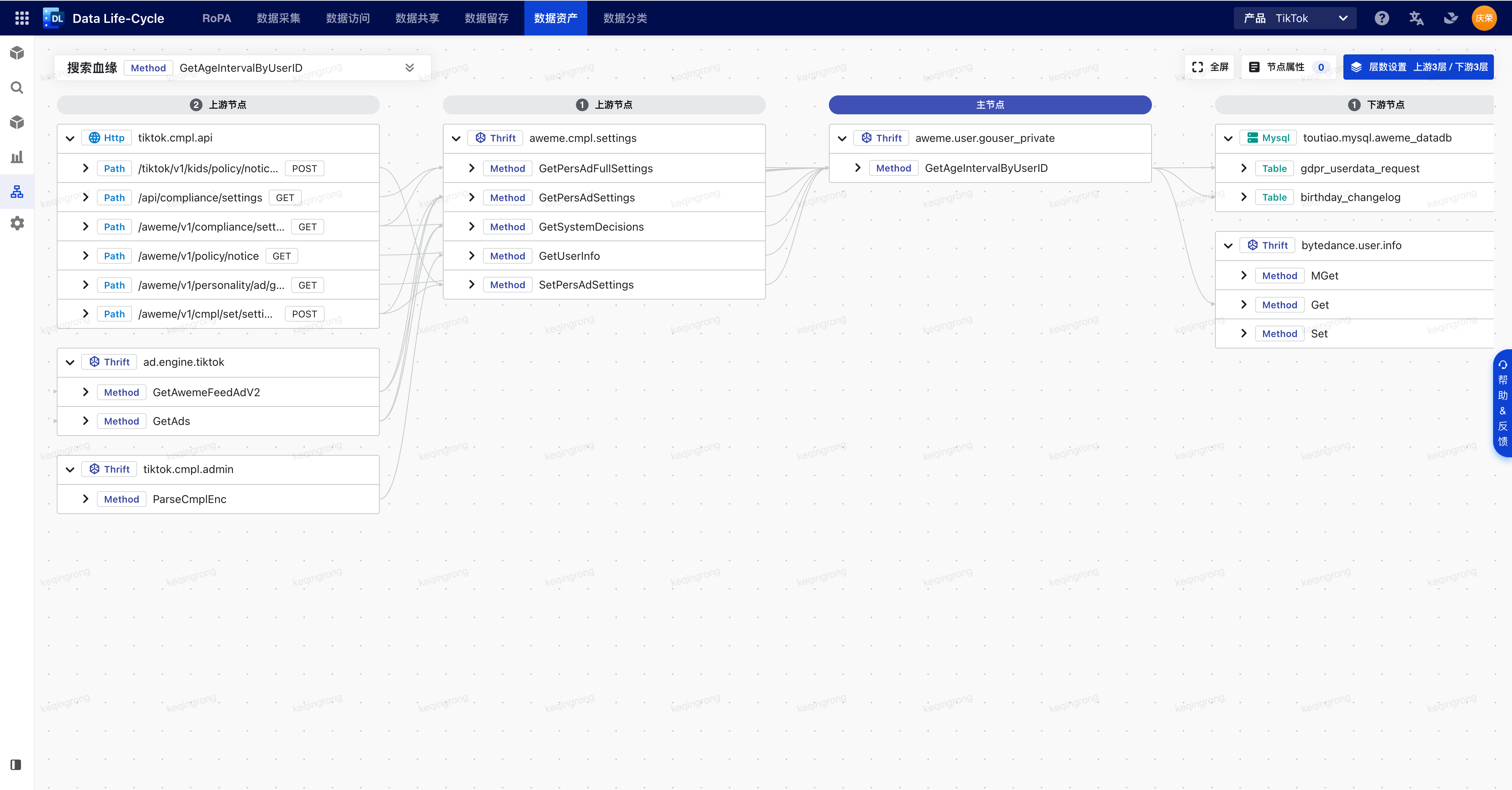
节选自笔者在团队内做的一次技术分享,介绍了2022年7月从零开发的第一版数据血缘拓扑图实现逻辑。特别说明,原文档为飞书文档,转成Markdown后,图例有所丢失。
背景
为什么选择自研拓扑图?
主要有两点原因:
- 业界缺少我们需要的拓扑图方案
常规的有向图基于节点,数据血缘拓扑图基于Tree,我们所要构建的图不局限于Graph with Asset Field Node,而希望和资产平台对齐,实现Graph with Asset PSM Tree。
- 缺少现成的布局算法
目前缺少成熟的类似层次布局算法(Dagre)、d3-hierarchy、力导向图布局算法(Force-directed graph)这样的布局算法,需要自行实现布局,计算各点坐标位置。
如何实现数据血缘拓扑图?
自研拓扑图需要解决的核心问题:
- 如何计算布局,生成节点位置坐标?
- 如何绘制边?
- 如何绘制节点?
如何计算布局
在绘制边之前,首先要进行布局计算,获取边的起始点和目标点的位置坐标。
主要有两种思路:
- 使用特定布局算法计算位置坐标,如层次布局算法、力导向图布局算法
- 交给浏览器布局,渲染后获取位置坐标
前期调研的可选方案都是基于这两种思路实现:
- Antv G6/X6、React Flow
使用 dagre 的层次布局算法,提前计算所有节点位置信息。
- @tiktok-woody/react-dag
使用 dagre 的层次布局算法计算节点位置,同时在节点挂载后将节点的ID和DOM引用保存到Store中,使得外层可以通过ID操作节点DOM,进而调整节点位置。
- Coral xGraph (DataLineageGraph)
节点的宽高固定,节点组的外间距固定,根据节点组的位置和节点的索引提前计算节点位置。滚动时基于节点组内滚动偏移量,重新计算节点位置。
本血缘拓扑图参考 Coral 的多列布局形式,因此无法使用 dagre 的层次布局算法,又因为需要支持自定义节点和做粗粒度节点展开,只能在节点渲染挂载后使用 getBoundingClientRect() 获取位置。滚动时可以综合原位置信息和滚动偏移量,或者重新调用 getBoundingClientRect() 获取最新位置。
如何同步布局
由于节点组内部支持垂直滚动,当用户滚动后需要同步最新的节点位置信息,重新绘制边。
-
上层被动接收下层节点在挂载后发布的宽高和位置数据(缺点:节点组滚动时,节点内部无法感知 scroll 事件)
-
上层主动获取下层节点的宽高和位置信息
- a. 自底向上:下层节点增加 DOM ID,上层使用
document.getElementById()获取节点 DOM(缺点:违背 React 设计原则) - b. 自底向上:下层节点增加 ref,借助 Context 传给上层,上层从 Context 中获取节点 DOM
- c. 自顶向下:上层为所有下层节点统一创建 ref,通过 Context 分发给下层节点,上层从 ref 集合中获取节点 DOM
- a. 自底向上:下层节点增加 DOM ID,上层使用
本血缘拓扑图采用方案2-b,布局变化后由上层主动调用DOM API获取下层节点的宽高和位置信息。
使用什么方案绘制边
获取起始点和目标点的位置坐标后便可以绘制边。
- 基于Canvas
- API:
lineTo()、quadraticCurveTo()、bezierCurveTo() - 代表:Coral xGraph (DataLineageGraph)、Antv G6
- 优势:高性能
- 劣势:只能通过Canvas API修改样式;事件监听只能绑定在Canvas容器上,需要手动分发事件。
- API:
- 基于SVG
- SVG元素:
<line>、<polyline>、<path> - 代表:@tiktok-woody/react-dag、Antv X6、React Flow
- 优势:矢量,支持缩放;支持CSS和DOM事件
- 劣势:节点数量到达一定量级后性能较差
- SVG元素:
本血缘拓扑图采用SVG方案,和Canvas相比,它支持定义边的鼠标事件,可以通过CSS控制样式。
注意:2022年7月数据血缘图的数据量最多只有几百个节点,边的数量大约是点的2.5倍;2023年3月,已经远远超出该数据量。
使用什么方案绘制节点
血缘拓扑图的节点绘制较为简单,采用 Semi Tree 实现 PSM -> Method -> Field 树,通过 renderFullLabel 属性接管树节点的渲染。
详细实现
组件设计
拓扑图节点、连线绘制层级
暂时无法在飞书文档外展示此内容
从下往上依次是:
- 背景层:绘制网格背景
- 连线层:绘制底层灰色连线
- 节点层:绘制节点,有跨层级连线时,上层节点将遮盖住连线
- 高亮连线层:绘制顶层蓝色连线,有跨层级连线时,连线将浮在节点上层
拓扑图数据源
图的数据源只需要包含构建节点和边的最基本字段。
interface Node<T> {
  id: string;
  data: T;
}

interface Edge<T> {
  source: string;
  target: string;
  data: T;
}
示例:
const data = {
  nodes: [
    {
      id: 'node1'
    },
    {
      id: 'node2'
    },
  ],
  edges: [
    {
      source: 'node1',
      target: 'node2'
    }
  ],
};
拓扑图组件结构
暂时无法在飞书文档外展示此内容
拓扑图组件 Props
interface Position {
  x: number;
  y: number;
}

interface Rect {
  width: number;
  height: number;
}

interface NodeProps {
  /** 节点唯一ID */
  id: string;
  /** 节点名称,可以同时存在于 data 字段中 */
  label?: string;
  /** 节点原点位置(左上角) */
  position?: Position;
  /** 节点宽高尺寸 */
  rect?: Rect;
  /** 节点数据 */
  data?: Record<string, unknown>;
  /** 子节点 */
  children?: Node[];
  /** 自定义节点渲染 */
  renderNode: (node: NodeProps) => RectNode;
  /** 节点点击回调 */
  onNodeClick: (node: NodeProps) => void;
  /** 节点展开回调 */
  onNodeExpand: (node: NodeProps) => void;
  /** 节点菜单选择回调  */
  onNodeContextMenuSelect?: (id: string, type: ContextMenuType) => void;
}

interface EdgeProps {
  /** 边唯一ID,默认使用 'source_target' 拼接 */
  id?: string;
  /** 起始点ID */
  source: string;
  /** 目标点ID */
  target: string;
  /** 边样式 */
  style?: CSSProperties;
}

interface ColumnProps {
  /** 上游/下游/终点 */
  type: 'upstream' | 'downstream' | 'endpoint';
  /** 层数,0表示当前节点/终点 */
  depth: number;
  /** 节点数据源 */
  nodes: NodeProps[];
  /** 自定义节点渲染 */
  renderNode: (node: NodeProps) => ReactNode;
  /** 节点点击回调 */
  onNodeClick: (node: NodeProps) => void;
  /** 节点展开回调 */
  onNodeExpand: (node: NodeProps) => void;
  /** 节点菜单选择回调  */
  onNodeContextMenuSelect?: (id: string, type: ContextMenuType) => void;
}

interface LineageGraphProps {
  /** 节点数据源 */
  nodes: NodeProps[];
  /** 边数据源 */
  edges: EdgeProps[];
  /** 主节点ID */
  primaryNodeId?: string;
  /** 展示层级 */
  level?: number;
  /** 自定义节点渲染 */
  renderNode: (node: NodeProps) => RectNode;
  /** 自定义遍渲染 */
  renderEdge: (edge: EdgeProps) => RectNode;
  /** 节点点击回调 */
  onNodeClick: (node: NodeProps) => void;
  /** 节点展开回调 */
  onNodeExpand: (node: NodeProps) => void;
  /** 节点菜单选择回调  */
  onNodeContextMenuSelect?: (id: string, type: ContextMenuType) => void;
}
LineageGraph JSX 示例代码:
<LayoutProvider>
  <EdgeProvider>
    <EdgeLayer edges={edges} />
    <HighlightedEdgeLayer edges={highlightedEdges} />
    <NodeLayer nodes={aggregatedNodes} />
  </EdgeProvider>
<LayoutProvider/>
其中
- LayoutProvider 用于提供节点布局信息,如坐标位置、宽高、DOM引用
- EdgeProvider 用于提供边的绘制信息,如是否已经绘制
坐标系换算
HTML、SVG、Canvas 都以页面的左上角为 (0, 0) 坐标点(原点),坐标以像素为单位,x 轴正方向是向右,y 轴正方向是向下。
由于 HTML 中 Event 事件、getBoundingClientRect() 获取的坐标位置始终相对于页面原点,当页面发生滚动后,获取的坐标并不能反映节点、连线在 SVG 容器中的真实位置,因此布局计算的全部坐标都需要相对 SVG 容器左上角原点做一定偏移。
interface Rect {
  width: number;
  height: number;
  x: number;
  y: number;
}

export const translate = (position?: DOMRect, origin = { x: 0, y: 0 }): Rect | undefined => {
  if (!position) {
    return undefined;
  } else {
    return {
      width: position.width,
      height: position.height,
      x: position.x - origin.x,
      y: position.y - origin.y,
    };
  }
};

// 起点原始Rect
const rect1 = ...
// 终点原始Rect
const rect2 = ...

// 起点坐标
const p1 = useMemo(() => translate(rect1, origin), [rect1, origin]);
// 终点坐标
const p2 = useMemo(() => translate(rect2, origin), [rect2, origin]);
分层
层级计算方案
以下分层方案按“主节点模式”说明。“起止点模式”层级计算方式和主节点模式类似,起始点记为0层,终止点记为Infinity无穷大层,将起点作为主节点计算层级。
方案一:按边的关系累加计算
主节点记为0层,以下游层级计算为例,和主节点有直接边关系的点,记为下游1层,和下游1层有直接边关系记为下游2层,依此类推。如果某节点已经赋过层级,有新的边关系时不再重新计算。
方案二:按节点和主节点的最短路径计算
基于Dijkstra算法(不允许有环)。
方案三:按节点和主节点的“最长路径”计算
无高效算法,有环的情况下无最长路径。
分层案例
案例1:3个节点
边关系:A -> B,A -> C,B -> C,其中A为主节点。
| 方案 | 示意图 |
|---|---|
| 按最短路径计算,B、C是下游1层。 | 暂时无法在飞书文档外展示此内容 |
| 按最长路径计算,B是下游1层,C是下游2层。 | 暂时无法在飞书文档外展示此内容 |
案例2:4个节点
边关系:A -> B,B -> C,C -> D,A-> D,其中A为主节点。
| 方案 | 示意图 |
|---|---|
| 按最短路径计算,B、D是下游1层,C是下游2层。 | 暂时无法在飞书文档外展示此内容 |
| 按最长路径计算,B是下游1层,C是下游2层,D是下游3层。 | 暂时无法在飞书文档外展示此内容 |
| 按边关系累加计算,情况1同最短路径;情况2,B、C、D是下游1层。(避免了图中出现从右到左的反向箭头) | 暂时无法在飞书文档外展示此内容 |
案例3:5个节点
边关系:A -> B,B -> C,C -> D,A -> E,E -> D,其中A为主节点。
| 方案 | 示意图 |
|---|---|
| 按最短路径计算,B、E是下游1层,C、D是下游2层。 | 暂时无法在飞书文档外展示此内容 |
| 按最长路径计算,B、E是下游1层,C是下游2层,D是下游3层。 | 暂时无法在飞书文档外展示此内容 |
| 按边关系累加计算,结果同最短路径。 | 暂时无法在飞书文档外展示此内容 |
代码实现
import { Node, Edge, GraphDataSource } from '../types';

interface DepthResult {
  depth2ids: Record<number, string[]>;
  id2depth: Record<string, number>;
}

/**
 * 主节点模式血缘图分层计算(按边关系累加计算)
 */
export const calcSingleGraphDepths = (graph: GraphDataSource, primaryId: string): DepthResult => {
  const id2depth: Record<string, number> = { [primaryId]: 0 };
  const depth2ids: Record<number, string[]> = {};
  const { nodes, edges } = graph;

  // 已经进行过分层,直接使用已有的depth
  const depthCalculated = nodes.find((node: Node) => typeof node.data?.depth === 'number');
  if (depthCalculated) {
    nodes.forEach((node: Node) => {
      if (typeof node.data?.depth === 'number') {
        const depth = node.data.depth;
        if (depth2ids[depth]) {
          depth2ids[depth].push(node.id);
        } else {
          depth2ids[depth] = [node.id];
        }
      }
    });
  } else {
    // 保证主节点Tree上所有节点depth都为0
    let primaryIdRootId = primaryId;
    const primaryNode = nodes.find((node: Node) => node.id === primaryId);
    if (primaryNode?.data) {
      primaryIdRootId = primaryNode.data.rootId;
    }
    const primaryNodeList = nodes.filter((node: Node) => node?.data?.rootId === primaryIdRootId);
    primaryNodeList.forEach((node: Node) => {
      id2depth[node.id] = 0;
    });

    // 计算当前节点直接上下游的相对层级
    const calcRelativeDepth = (id: string, depth = 0) => {
      if (depth2ids[depth]) {
        depth2ids[depth].push(id);
      } else {
        depth2ids[depth] = [id];
      }

      // 查找直接上下游
      const keys = Object.keys(id2depth);
      const associatedEdges = edges.filter(({ source, target }: Edge) => {
        return (source === id && !keys.includes(target)) || (target === id && !keys.includes(source));
      });

      const associatedNodeDepthMap: Record<string, number> = {};

      // 计算当前节点上下游层级
      associatedEdges.forEach(({ source, target }: Edge) => {
        const associatedNodeId = source === id ? target : source;
        let associatedNodeDepth = source === id ? depth + 1 : depth - 1;
        if (associatedNodeDepth === 0) {
          // 当下级或上级同主节点相同的层级,将其往上或者下层放
          associatedNodeDepth = source === id ? depth - 1 : depth + 1;
        }
        if (!id2depth[associatedNodeId]) {
          id2depth[associatedNodeId] = associatedNodeDepth;
        }
        // 保存当前节点上下游
        associatedNodeDepthMap[associatedNodeId] = associatedNodeDepth;
      });

      // 计算上下游的上下游
      Object.entries(associatedNodeDepthMap).forEach(([nodeId, nodeDepth]) => {
        calcRelativeDepth(nodeId, nodeDepth);
      });
    };

    calcRelativeDepth(primaryId);
  }

  return {
    depth2ids,
    id2depth,
  };
};
粒度聚合和展开
PSM 粒度展开
初始为PSM粒度:
暂时无法在飞书文档外展示此内容
PSM展开后:边关系保持PSM粒度,不额外请求Method、Field粒度边关系数据
暂时无法在飞书文档外展示此内容
Field 粒度聚合
初始为Field粒度:
暂时无法在飞书文档外展示此内容
Field聚合成PSM后:节点按PSM-Method-Field形式渲染,边关系保持Field粒度
暂时无法在飞书文档外展示此内容
数据聚合实现
示例数据,处理前:
// `path_info` 为父级节点列表
const nodes = [
  { id: 'aaa', path_info: [{ id: 'a' }, { id: 'aa' }] },
  { id: 'baa', path_info: [{ id: 'b' }, { id: 'ba' }] },
  { id: 'bab', path_info: [{ id: 'b' }, { id: 'ba' }] },
  { id: 'bac', path_info: [{ id: 'b' }, { id: 'ba' }] },
  { id: 'bba', path_info: [{ id: 'b' }, { id: 'bb' }] },
  { id: 'caa', path_info: [{ id: 'c' }, { id: 'ca' }] }
];

const edges = [
  { source: 'aaa', target: 'baa' },
  { source: 'aaa', target: 'bab' },
  { source: 'aaa', target: 'bac' },
  { source: 'aaa', target: 'bba' },
  { source: 'aaa', target: 'caa' }
];
示例数据,处理后:
const aggregatedNodes = [
  {
    id: 'a',
    children: [{ id: 'aa', children: [{ id: 'aaa' }] }]
  },
  {
    id: 'b',
    children: [
      { id: 'ba', children: [{ id: 'baa' }, { id: 'bab' }, { id: 'bac' }] },
      { id: 'bb', children: [{ id: 'bba' }] }
    ]
  },
  {
    id: 'c',
    children: [{ id: 'ca', children: [{ id: 'caa' }] }]
  }
];

const aggregatedEdges = [
  { source: 'a', target: 'b' },
  { source: 'a', target: 'c' }
];
代码实现:
import { NodeVariantData, NodeVariant, EdgeVariant } from './types';

interface Options {
  nodes?: NodeVariant<NodeVariantData>[];
  edges?: EdgeVariant[];
}

interface Result {
  nodes: NodeVariant[];
  edges: EdgeVariant[];
}

/**
 * 对血缘图数据源进行聚合,将扁平数据处理成psm->method->field树形数据
 */
export const aggregate = ({ nodes = [], edges = [] }: Options): Result => {
  const nodeMap: Record<string, NodeVariant> = {};
  const aggregatedNodes: NodeVariant[] = [];
  const aggregatedEdges: EdgeVariant[] = [];

  // 聚合 node
  nodes.forEach((node) => {
    if (!nodeMap[node.id]) {
      nodeMap[node.id] = { ...node };
    }

    // 如果有祖先节点列表,则从左往右处理,第一个节点push到aggregatedNodes中,剩余节点作为前一个节点的子节点;
    // 如果没有祖先节点列表,则将当前节点push到aggregatedNodes中。
    const ancestors = node?.data?.ancestors ?? [];

    [...ancestors, node].reduce<NodeVariant | null>((previous, current) => {
      if (!nodeMap[current.id]) {
        nodeMap[current.id] = {
          id: current.id,
          label: current.label,
        };
      }
      const currentNode = nodeMap[current.id];

      if (!previous) {
        if (!aggregatedNodes.find((item) => item.id === current.id)) {
          aggregatedNodes.push(currentNode);
        }
      } else {
        (currentNode.data as NodeVariantData).parentId = previous.id;
        const previousNode = nodeMap[previous.id];
        if (!Array.isArray(previousNode.children)) {
          previousNode.children = [];
        }
        if (!nodeMap[previous.id].children?.find((child) => child.id === current.id)) {
          previousNode.children?.push(currentNode);
        }
      }
      return current;
    }, null);
  });

  const appendRootId = (list: NodeVariant[], rootId?: string) => {
    list.forEach((item) => {
      if (rootId) {
        (item.data as NodeVariantData).rootId = rootId;
      } else {
        (item.data as NodeVariantData).rootId = item.id;
      }
      if (Array.isArray(item.children)) {
        appendRootId(item.children, item.data?.rootId);
      }
    });
  };

  // 增加 rootId,方便聚合 edge
  appendRootId(aggregatedNodes);

  // 聚合 edge
  edges.forEach((edge) => {
    const source = nodeMap[edge.source]?.data?.rootId;
    const target = nodeMap[edge.target]?.data?.rootId;
    if (source && target) {
      const id = `${source}_${target}`;
      if (!aggregatedEdges.find((item) => item.id === id)) {
        aggregatedEdges.push({
          id,
          source,
          target,
        });
      }
    }
  });

  return {
    nodes: aggregatedNodes,
    edges: aggregatedEdges,
  };
};
边的绘制
SVG 路径绘制
如果想了解更多,可以参考如下链接:
- MDN path 教程 https://developer.mozilla.org/en-US/docs/Web/SVG/Tutorial/Paths
- SvgPathEditor https://yqnn.github.io/svg-path-editor/
- 三次贝塞尔曲线动画 https://cubic-bezier.com/
| SVG元素 | 说明 | 示例代码 |
|---|---|---|
<line> |
用于创建一条连接两个点的直线。 主要属性: - x1 定义起点x坐标 - x2 定义起点y坐标 - y1 定义终点x坐标 - y2 定义终点y坐标 | <svg viewBox="0 0 100 100" xmlns="http://www.w3.org/2000/svg"> <line x1="0" y1="80" x2="100" y2="20" stroke="black" /> </svg> |
<polyline> |
用于创建多段直线。 主要属性: - points 定义需要绘制的点的x、y坐标列表 | <svg viewBox="0 0 200 100" xmlns="http://www.w3.org/2000/svg"> <polyline points="100,100 150,25 150,75 200,0" fill="none" stroke="black" /> </svg> |
<path> |
用于创建复杂的SVG形状。 主要属性: - d 定义绘制的路径命令列表 | <svg viewBox="0 0 100 100" xmlns="http://www.w3.org/2000/svg"> <path fill="none" stroke="red" d="M 10,30 A 20,20 0,0,1 50,30 A 20,20 0,0,1 90,30 Q 90,60 50,90 Q 10,60 10,30 z" /> </svg> |
SVG 定义了六种路径命令类型,一共 20 条命令:
- 移动到(Move To):M、m
- 画线到(Line To):L、l、H、h、V、v
- 三次贝塞尔曲线(Cubic Bézier Curve):C、c、S、s
- 二次贝塞尔曲线(Quadratic Bézier Curve):Q、q、T、t
- 弧线/椭圆曲线(Arc):A、a
- 封闭路径:Z、z
SVG 代码
<!-- 普通边 -->
<svg class="edge-layer">
  <defs>
    <!-- 箭头 -->
    <marker
      id="arrow"
      viewBox="0 -5 10 10"
      refX="9"
      refY="0"
      markerWidth="5"
      markerHeight="5"
      orient="auto"
    >
      <path d="M 0,-5 L 10,0 L 0,5" stroke="#C6CACD" fill="#C6CACD" />
    </marker>
  </defs>
  <!-- 一条终点为箭头的边 -->
  <path d="M 920,105 C 960,105 960,105 1000,105" class="path-curve" marker-end="url(#arrow)"></path>
</svg>

<!-- 高亮边 -->
<svg class="edge-layer">
  <defs>
    <!-- 高亮箭头 -->
    <marker
      id="arrow-highlighted"
      viewBox="0 -5 10 10"
      refX="9"
      refY="0"
      markerWidth="5"
      markerHeight="5"
      orient="auto"
    >
      <path d="M 0,-5 L 10,0 L 0,5" stroke="#0077FA" fill="#0077FA" />
    </marker>
  </defs>
  <!-- 一条终点为高亮箭头的边 -->
  <path d="M 920,106 C 960,106 960,105 1000,105" class="path-curve path-active" marker-end="url(#arrow-highlighted)"></path>
</svg>
CSS 代码
.edge-layer {
  width: 100%;
  height: 100%;
}

.edge-layer-highlighted {
  pointer-events: none;
}

.path-curve {
  fill: none;
  stroke: #c6cacd;
  stroke-width: 1;
}

.path-active {
  stroke: #0e42d2;
  stroke-dasharray: 4;
  stroke-width: 1;
}
SVG 动画
采用 CSS 动画实现,通过周期性修改 stroke dash array 的偏移量。
@keyframes dash {
  from {
    stroke-dashoffset: 60;
  }
  to {
    stroke-dashoffset: 10;
  }
}

.path-curve {
  fill: none;
  stroke: #c6cacd;
  stroke-width: 1;
}

.path-active {
  stroke: #0e42d2;
  stroke-dasharray: 4;
  stroke-width: 1;
  animation: dash 4s linear infinite normal;
}
边的绘制场景
| 边关系 | 场景:A、B同列 | 场景:A、B相邻列 | 场景:A、B跨列 |
|---|---|---|---|
| A->A | 暂时无法在飞书文档外展示此内容 暂时无法在飞书文档外展示此内容 | 无 | 无 |
| A->B,A、B同层 | 无 | 方案1:左入右出: 暂时无法在飞书文档外展示此内容 | 方案1:左入右出(不避让): 暂时无法在飞书文档外展示此内容 方案1:左入右出(避让): 暂时无法在飞书文档外展示此内容 |
| A->B,A、B不同层 | 方案1:左入右出: 暂时无法在飞书文档外展示此内容 方案2:从上往下时右入右出,从下往上时左入左出: 暂时无法在飞书文档外展示此内容 | 方案1:左入右出: 暂时无法在飞书文档外展示此内容 | 方案1:左入右出(不避让): 暂时无法在飞书文档外展示此内容 方案2:左入右出(避让): 暂时无法在飞书文档外展示此内容 |
| A->B, B->A | 方案1:左入右出: 暂时无法在飞书文档外展示此内容 方案2:从上往下时右入右出,从下往上时左入左出: 暂时无法在飞书文档外展示此内容 | 方案1:左入右出: 暂时无法在飞书文档外展示此内容 方案2:从上往下时右入右出,从下往上时左入左出: 暂时无法在飞书文档外展示此内容 方案3:出入共用一条边 暂时无法在飞书文档外展示此内容 | 方案1:左入右出: 暂时无法在飞书文档外展示此内容 方案2:从上往下时右入右出,从下往上时左入左出: 暂时无法在飞书文档外展示此内容 方案3:出入共用一条边(不避让): 暂时无法在飞书文档外展示此内容 方案4:出入共用一条边(避让): 暂时无法在飞书文档外展示此内容 |
折线实现
实现方式:
- 绘制方式:折线
- 出入方向:左入右出;若有反向调用,出入共用一条边
- 避让规则:跨列绘制时不避让同层节点
- 控制点:起点、终点、一个或两个中间点
import { Position, Rect } from '../types';

export interface Options {
  /** 起始点坐标 */
  start: Position & Rect;
  /** 终止点坐标 */
  end: Position & Rect;
  /** 间距 */
  gap?: number;
  /** 是否绘制自调用连线,默认 false */
  selfCall?: boolean;
  /** 当前起点和终点是否已被绘制过,默认 false */
  existEdge?: boolean;
  /** markerEnd x轴偏移量 */
  offsetX?: number;
}

/**
 * 绘制折线
 * - 需要计算起点、控制点1、控制点2、终点
 */
export const drawLine = (options: Options): string | null => {
  const { start: p1, end: p2, gap = 80, offsetX = 0, selfCall = false } = options;
  // 自调用取消绘制
  if (!selfCall && p1.x === p2.x && p1.y === p2.y) {
    return null;
  }
  // 间距和偏移量
  const dx = gap / 2 + offsetX;
  // 起点
  const start = {
    x: p1.x <= p2.x ? p1.x + p1.width : p1.x, // 起点在前|同列
    y: p1.y + p1.height / 2,
  };
  // 终点
  const end = {
    x: p1.x >= p2.x ? p2.x + p2.width : p2.x, // 终点在前|同列
    y: p2.y + p2.height / 2,
  };
  if (p1.x === p2.x && p1.y === p2.y) {
    // 自调用
    start.y = p1.y + p1.height / 4;
    end.y = p2.y + (p2.height * 3) / 4;
  }
  const middle1 = {
    x: p1.x <= p2.x ? start.x + dx : end.x + dx,
    y: start.y,
  };
  const middle2 = {
    x: middle1.x,
    y: end.y,
  };
  if (p1.x !== p2.x && p1.y === p2.y) {
    // 不同列同一行
    return `M ${start.x},${start.y} ${end.x},${end.y}`;
  }
  // 自调用|同一列|不同列不同行
  return `M ${start.x},${start.y} ${middle1.x},${middle1.y} ${middle2.x},${middle2.y} ${end.x},${end.y}`;
};
三次贝塞尔曲线绘制实现
实现方式:
- 绘制方式:三次贝塞尔曲线
- 出入方向:左入右出;若有反向调用,出入共用一条边
- 避让规则:跨列绘制时不避让同层节点
- 控制点:起点、起点控制点、终点、终点控制点
import { Position, Rect } from '../types';

export interface Options {
  /** 起始点坐标 */
  start: Position & Rect;
  /** 终止点坐标 */
  end: Position & Rect;
  /** 间距 */
  gap?: number;
  /** 是否绘制自调用连线,默认 false */
  selfCall?: boolean;
  /** 当前起点和终点是否已被绘制过,默认 false */
  existEdge?: boolean;
  /** markerEnd x轴偏移量 */
  offsetX?: number;
}

/**
 * 绘制三次贝塞尔曲线
 *  需要计算起点、起点控制点、终点、终点控制点
 */
export const drawCurve = (options: Options): string | null => {
  const { start, end, gap = 0, selfCall = false, existEdge = false } = options;
  // 自调用取消绘制
  if (!selfCall && start.x === end.x && start.y === end.y) {
    return null;
  }
  // 起点
  const x1 = start.x <= end.x ? start.x + start.width : start.x;
  const y1 = start.y + start.height / 2;
  // 终点
  const x2 = start.x >= end.x ? end.x + end.width : end.x;
  const y2 = end.y + end.height / 2;
  // 起点控制点、终点控制点
  let [xcs, ycs, xce, yce]: number[] = [x1, y1, x2, y2];
  if (start.x < end.x) {
    // 起点在前,终点在后
    const dx = Math.abs(x2 - x1) / 2;
    if (existEdge) {
      if (y1 < y2) {
        // 起点在上
        ycs = y1 + dx;
      } else if (y1 === y2) {
        const dx1 = Math.abs(x1 - x2) / 3;
        // 从上方圆弧过去
        xcs = x1 + dx1;
        ycs = y1 - dx1;
        xce = x2 - dx1;
        yce = y2 - dx1;
      } else {
        // 起点在下
        ycs = y1 - dx;
      }
    } else {
      xcs = x1 + dx;
    }
    xce = x2 - dx;
    return `M ${x1},${y1} C ${xcs},${ycs} ${xce},${yce} ${x2},${y2}`;
  } else if (start.x > end.x) {
    // 终点在前,起点在后
    const baseDistanceX = Math.abs(x1 - x2);
    const baseDistanceY = Math.abs(y1 - y2);
    const dx = baseDistanceX / 2;
    if (existEdge) {
      if (baseDistanceY < 20 || y1 === y2) {
        // 从下方圆弧过去
        const dx1 = baseDistanceX / 3 + baseDistanceY;
        xcs = x1 - dx1;
        ycs = y1 + dx1;
        xce = x2 + dx1;
        yce = y2 + dx1;
      } else if (y1 < y2) {
        // 起点在上
        ycs = y1 + dx;
      } else {
        // 起点在下
        ycs = y1 - dx;
      }
    } else {
      xcs = x1 - dx;
    }
    xce = x2 + dx;
    return `M ${x1},${y1} C ${xcs},${ycs} ${xce},${yce} ${x2},${y2}`;
  } else if (start.x === end.x) {
    // 同一列
    const dex = gap / 2;
    if (start.y === end.y) {
      // 自调用
      xcs = x1 + dex * 2;
      xce = x2 + dex * 2;
      ycs = y1 - dex * 2;
      yce = y2 + dex * 2;
    } else {
      // 控制点计算
      const r = Math.abs(y2 - y1) / 4;
      if (existEdge) {
        xcs = x1 + dex / 2;
        xce = x2 + dex / 2;
      } else {
        xcs = x1 + dex;
        xce = x2 + dex;
      }
      if (start.y < end.y) {
        // 同列起点在上
        ycs = y1 + r;
        yce = y2 - r;
      } else {
        // 同列起点在下
        ycs = y1 - r;
        yce = y2 + r;
      }
    }
    return `M ${x1},${y1} C ${xcs},${ycs} ${xce},${yce} ${x2},${y2}`;
  }
  return null;
};
上下游展开和收起
如何判断是否支持展开和收起上下游
- 展开上游:节点本身是主节点、终点或者上游节点(即 node.depth <= 0),有潜在上游且上游没有被展开。
- 收起上游:节点本身是主节点、终点或者上游节点(即 node.depth <= 0),有潜在上游且上游已经被展开。
- 展开下游:节点本身是主节点或者下游节点(即 node.depth >= 0 且 node 非终点),有潜在下游且下游没有被展开。
- 收起下游:节点本身是主节点或者下游节点(即 node.depth >= 0 且 node 非终点),且有潜在下游且下游已经被展开。
上下游展开和收起实现方案
方案一:修改原始数据源
- 优点
- 不需要考虑被展开/收起节点的粒度。
- 收起时,不需要处理上游的上游或者下游的下游。
- 缺点
- 布局不稳定,有新的边数据加入,会导致重新分层,节点的层级可能会变动。
- 详细说明
- 展开上游:查找所有 target 为被展开节点 id 的边,添加到 edges,这些边的 source 添加到 nodes。
- 收起上游:查找所有 target 为被收起节点 id 的边,从 edges 中移除,这些边的 source 标记为 upstreamIds ,其中 depth < node.depth 的节点从 nodes 移除,其余节点保留。
- 展开下游:查找所有 source 为被展开节点 id 的边,添加到 edges,这些边的 target 添加到 nodes。
- 收起下游:查找所有 source 为被收起节点 id 的边,从 edges 中移除,这些边的 target 标记为 downstreamIds ,其中 depth > node.depth 的节点从 nodes 移除,其余节点保留。
方案二:修改聚合和分层后的数据
- 优点
- 布局稳定,加入新的边不会影响已有节点位置。
- 缺点
- 计算复杂,需要计算被展开/收起节点的边关系、所有上下游关系。
- 详细说明
- 略
本血缘拓扑图采用方案1,上下游关系计算逻辑简单。
实现效果